Startseite > ice storage > TSU-M: Internal melt
Ice storage | TSU-M
TSU-M: Internal melt
The TSU-M is an ice storage unit for internal melting with glycol injection for a power range from 647 to 2,676 kWh. This system is mainly used for air conditioning systems.
Operating principle
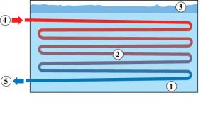
The TSU-M is an internal melting system that produces and builds ice (1) around a bundle of tubes (2) immersed in water (3), much of which freezes in the tank. The warm glycol (4) from the load flows through the tube bundle and melts the ice from the inside. The newly cooled glycol (5) is then pumped through the building’s cooling system or used to cool a secondary refrigerant. Internal melting is ideal for air conditioners that include cooling at higher temperatures during external melting.
Main advantages
- Lowest investment costs
- Reduction of energy costs
- Reliable operation
Main advantages in detail
By designing the cooling system on the basis of the average cooling demand and not oriented to the load peaks, the entire cooling system (chiller, pump, piping) can be dimensioned smaller. The fact that smaller cooling systems also require less refrigerant is not only economical but also environmentally friendly.
On the one hand, a smaller cooling system saves energy. In addition, the ice storage system enables low-cost night electricity tariffs to be used and less electricity to be consumed at high prices during the day. In addition, when ice is built up at night, the outside temperatures are also lower, which also saves energy.
For decades, ice storage technology has proven itself in thousands of cooling systems. It offers constant supply temperatures independent of cooling requirements. Minimal maintenance requirements, which can also be carried out during the day, increase system availability.
The raw bundles of the ice accumulator consist of steel smooth coils with a continuous outer diameter of 26.7 mm. They are mounted in a steel frame, which carries their weight during full ice build-up. After production, the tube bundles are tested for leaks with compressed air at a pressure of 13 bar under water and then hot-dip galvanized against corrosion. The coils are arranged to allow counterflow glycol flow in adjacent circuits for maximum storage capacity.
Individual tube bundles can also be manufactured in two modules at the factory to optimise transport costs and reduce assembly time on site. The glycol distributors are coated in the factory with a cold-galvanized surface. Necessary profiles and lifting eyes are attached to the tube bundles to allow lifting and final positioning in the storage tank.
Most climate applications use a daily load profile consisting of the hourly display of cooling loads over a period of 24 hours to determine the amount of storage required. Some air conditioning systems apply a weekly load profile. For conventional air conditioning systems, cooling machines are designed on the basis of the peak cooling load. In ice storage systems, the chillers are selected on the basis of the kWh value required for cooling and a defined operating strategy. Ice storage systems provide much flexibility for different operating strategies as long as the selected total kWh value is not exceeded. For this reason, an exact load profile must be specified when designing an ice storage system.
Once the load profile has been created, an operating strategy is defined when the ice storage devices are selected, i.e. the hours per day during which the glycol chiller can be operated are determined. Which operating strategy is used depends on the load profile (the application), the tariff structure of the utility company, the energy costs and the equipment acquisition costs. In other words, the economic balance between system installation and operating costs or payback time must be calculated. There are two different operating strategies, either full or partial storage.
Full storage systems store the entire cooling capacity required during off-peak hours and eliminate the need to operate chillers during the utility’s peak hours. This strategy shifts most of the electricity demand and leads to the lowest operating costs. However, due to the large chiller and storage requirements, the equipment acquisition costs are considerably higher than for partial storage systems and are therefore rarely used.
In the case of partial storage systems, the chillers are also operated during peak times. The partial storage system, where the glycol chiller runs 24 hours a day at full capacity, is the most commonly used because it results in the smallest chiller selection. In many cases, the smaller selection of chillers is the reason for an ice storage system. Lower electrical drive power, lower refrigerant charge, smaller cooling towers or other heat exchangers (less noise), smaller standby chillers (if required), lower capital and maintenance costs are other key selection criteria.
Other partial storage operating strategies switch off the chiller a few hours a day if the electricity costs are high and/or if a lot of electricity is important for other purposes (i.e. if the chiller operation would increase the demand for electricity). The fewer hours the chiller is in operation per day, the larger it must be. In addition, the storage device must be enlarged if the chiller is switched off during the cooling period. If the chiller is switched off during the non-cooling period, the ice build-up time is reduced and therefore lower glycol temperatures are required and the coefficient of performance (COP) of the chiller is reduced.
In addition to determining when the chiller should run or shut down, another aspect of the operating strategy is whether the chiller or the ice is given priority during melting to cover the existing cooling load.
With a chiller priority system, the chiller always operates at full capacity. If the cooling load exceeds the capacity of the chiller, the rest is covered by the melting ice. A constant part of the load is covered by the chiller, while the fluctuation of the load is covered by the ice.
In an ice priority system, a constant part of the load is covered by the ice, while the chiller takes over the fluctuation of the load. Since the chiller does not work at maximum capacity all the time, it is oversized compared to the chiller priority system. Ice priority systems lead to oversized ice and refrigeration machine selection and are therefore rarely used.
Normal practice is that partial storage systems with chiller priority and 24-hour chiller operation are most frequently used.
In this operating mode, ice is built up by circulating a 25% solution of water and glycol (by weight) with inhibitors at minus temperatures through the raw bundles of ice storage. The operating conditions of the chiller are monitored and it is switched off when the minimum glycol supply temperature is reached outside the chiller. A device for measuring the amount of ice for controlling the refrigerating machine is available as an option.
If a cooling load is present during ice formation, part of the cold glycol used for ice formation is diverted to the cooling load to provide the required cooling. The amount of glycol diverted is determined by the target temperature of the building circuit.
When the chiller is off, the warm reflux glycol solution is cooled to the desired temperature by melting ice stored in the modular ice storage unit.
Accordeon Content
In this operating mode, the chiller supplies all cooling requirements of the building. The glycol flow is routed around the ice storage device so that the cold glycol can flow directly to the cooling load. The temperature setpoints are maintained by the chiller.
In this operating mode, cooling is provided by a combined operation of chiller and ice storage device. The glycol chiller pre-cools the warm reflux glycol. The pre-cooled glycol solution then flows through the ice storage device, where it is cooled from the ice to the design temperature.

